EKR0 2P Tuya Wifi Smart RCBO with Metering
Inquire
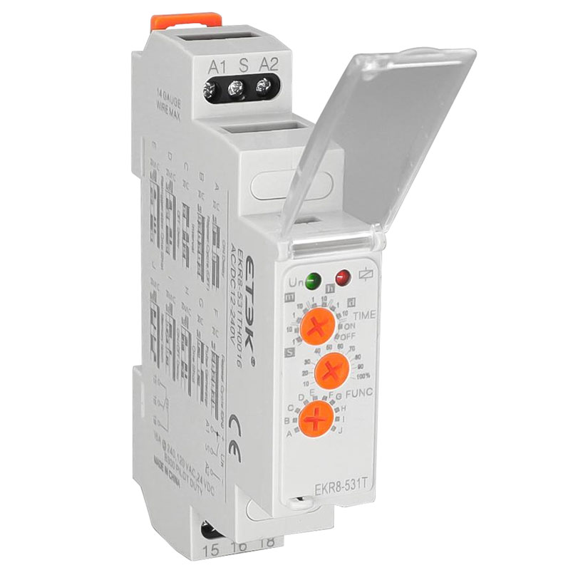
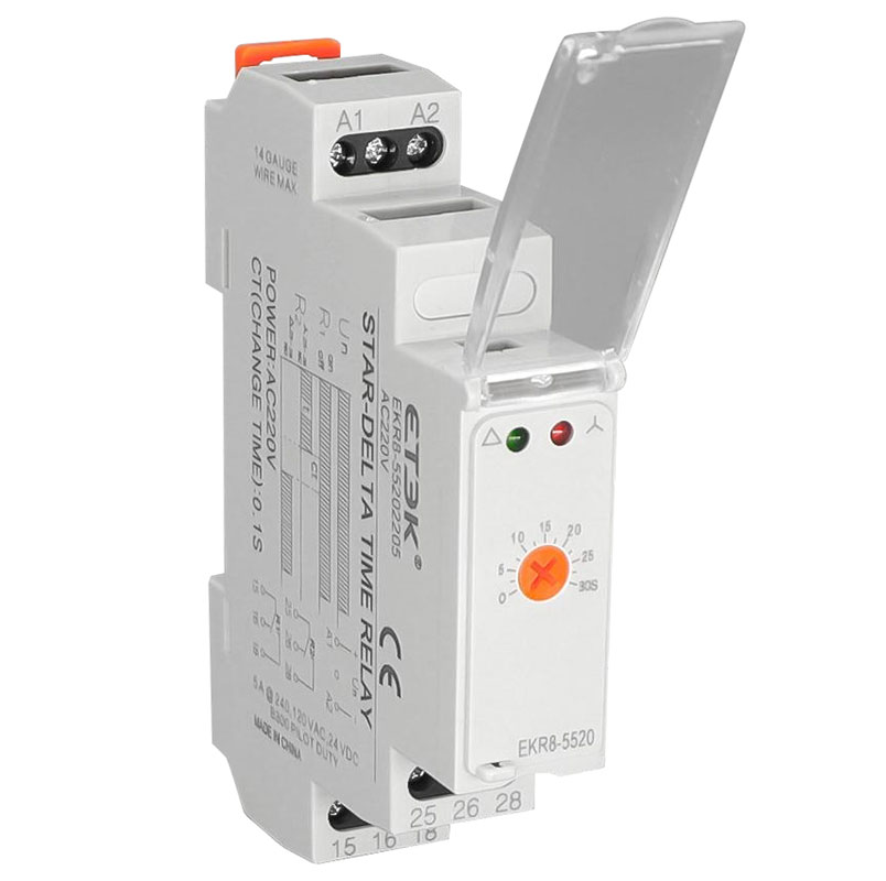
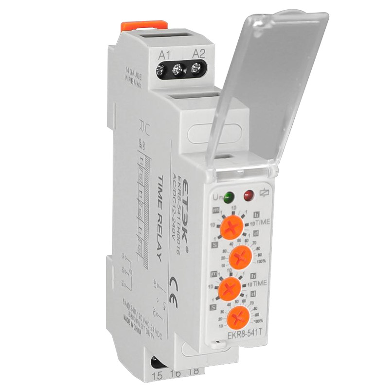
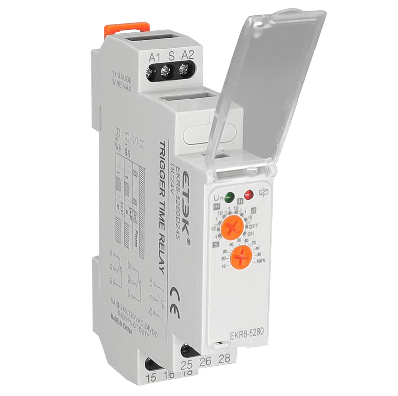
Time relay is an automatic control unit, that can be combined with various other electrical equipment to achieve automatic control of the operating circuit. After a preset time expires, the contact output will be closed or opened, which will enable the terminal electrical equipment to automatically run or stop.
This series of time relay has the advantages of wide operating voltage range, clear workinginstructions, small volume, uniform size, easy installation, etc.
Industrial machinery
lllumination
Manufacturing
HVAC system
Food and agriculture
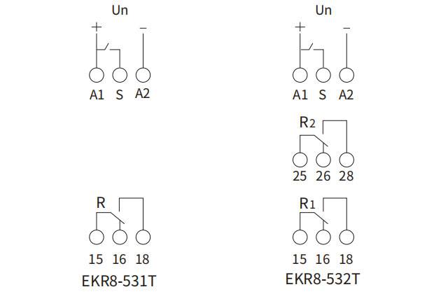
| Multi-function Time Relay | EKR8-5 Series |
 |
|
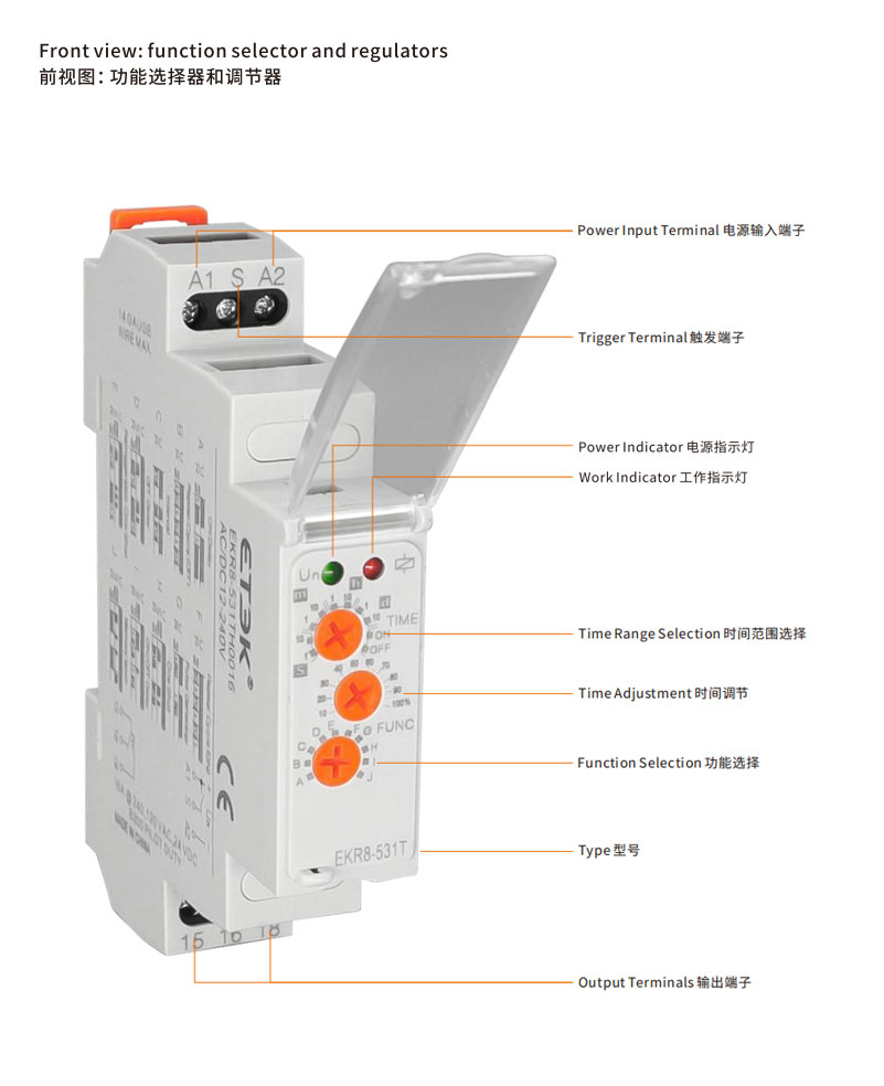
| Output Characteristics | EKR8-531T |
| Output Characteristics | SPDT |
| Contact Material | Silver Alloy |
| Current Rating | 16A@240VAC, 24VDC |
| Minimum Switching Requirement | 100mA |
| Input Characteristics | |
| Voltage Range | 12-240VAC/DC |
| Contact Material | Silver Alloy |
| Operating Range(% of Nominal) | 85%-110% |
| Timing Characteristics | |
| Functions Available | 10 |
| Time Scales | 10 |
| Time Ranges | 0.1s~10D |
| Minimum Switching Requirement | 100mA |
| Tolerance(Mechanical Setting) | 5% |
| Reset Time | 150ms |
| Trigger Pulse Length(Minimum) | 50ms |
| Environment | |
| Ambient Temperature around the device | Storage: -30℃~+70℃℃ (-22℉~ +158℉) Operation: -20℃~+55°℃ (-4℉~ +131℉) |
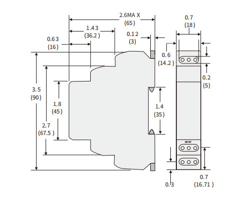
| Dimensions: in(mm) | Wiring Diagrams |
 |
 |
| Function | Operation | Timing Chart |
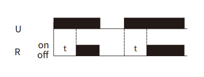
| A On Delay Power on |
When the input voltage U is applied, timing delay t begins. Relay contacts R change state after time delay is complete. Contacts R return to their shelf state when input voltage U is removed. Trigger switch is not used in this function. |
 |
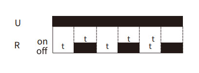
| B Repeat Cycle Starting Off |
When the input voltage U is applied, timing delay t begins. When time delay t is complete, relay contacts R change state for time delay t. This cycle will repeat until input voltage U is removed. Trigger switch is not used in this function. |
 |
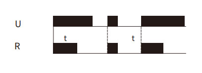
| C Interval Power On |
When input voltage U is applied, relay contacts R change state Immediately and timing cycle begins. When time delay is complete, contacts return to shelf state, When input voltage U is removed, contacts will also return to their state. Trigger switch is not used in this function. |
 |
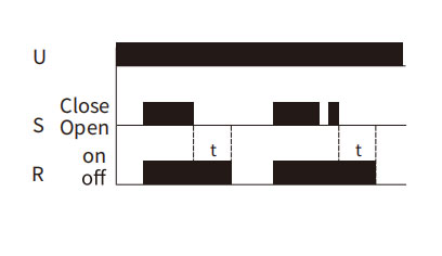
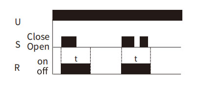
| D Off Delay S Break |
Input voltage U must be applied continuously. When trigger S is closed. relay contacts R change state. When trigger S is opened, delay t begins. When delay t is complete, contacts R return to their shelf state. lf trigger S is closed before time delay t is complete, then time is reset. When trigger S is opened, the delay begins again, and relay contacts remain in their energized state, if input voltage U is removed, relay contacts R return to their shelf state. |
 |
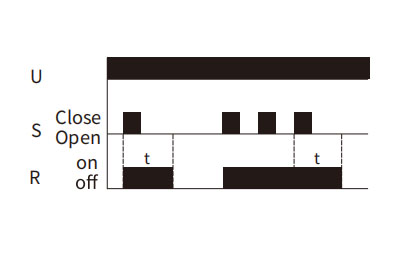
| E Retriggerable One Shot |
Upon application ofinput voltage U, the relay is ready to accept trigger signal S. upon application of the trigger signal S, the relay contacts R transfer and the preset time t begins. At the end of the preset time t, the relay contacts R return to their normal condition unless the trigger signal S is opened and closed prior to time out t (before preset time elapses). Continuous cycling of the trigger signal S at a rate faster than the preset time will cause the relay contacts R to remain closed. lf input voltage U is removed, relay contacts R return to their shelf state. |
 |
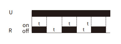
| F Repeat Cycle Starting ON |
When input voltage U is applied, relay contacts R change state immediately and time delay t begins. When time delay t is complete, contacts return to their shelf state for time delay t. This cycle will repeat until input voltage U is removed. Trigger switch is not used in this function. |
 |
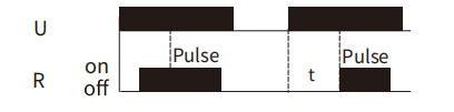
| G Pulse Generator |
Upon application ofinput voltage U ,a single output pulse of 0.5 seconds is delivered to relay offer time delay t. Power must be removed and reapplied to repeat pulse. Trigger switch S is not used in this function. |
 |
| H One Shot |
Upon application of input voltage U , the relay is ready to accept trigger signal S. Upon application of the trigger signal S, the relay contacts R trasher and the preset time t begins. During time-out, the trigger signal S is ignored. The relay resets by applying the trigger signal S when the relay is not energized. |
 |
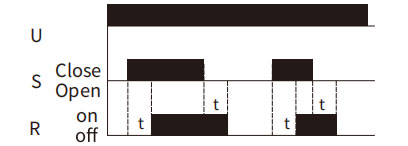
| I On/off Delay S Make/Break |
Input voltage U must be applied continuously. When trigger S is closed, time delay t begins. When time delay t is complete, relay contacts R change state and remain transferred until trigger S is opened. lf input voltage U is removed, relay contacts R return to their shelf state. |
 |
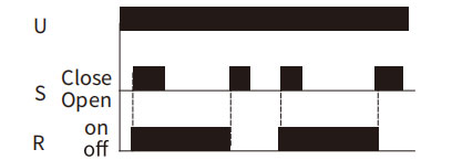
| J Memory Latch S Make |
Input voltage U must be applied continuously. Output changes state with every trigger S closure. lf input voltage U is removed, relay contacts R return to their shelfsate. |
 |
| Relay Contact 16A | Load | ||||||||
 |
 |
 |
 |
 |
AC1 | AC2 | AC1 5 | DC1(24/110/220V) | |
| AgNi | 100W | 4000V A | 0.9k W | 750VA | 16A/0.5A/0.35A | ||||

INQUIRY NOW!
ETEK is committed to providing the best service for our customers!


No.770 Wutun Fast Road,Anhui Xinwu Economic Development Zone,Wanzhi District,Wuhu City,Anhui Province,P.R.China.
E-mail : sales@etek-electric.com
Website : www.etek-electric.com
No.288 Wei 17th Road,Economic Development Zone,Yueqing City,Zhejiang China.
No.770 Wutun Fast Road,Anhui Xinwu Economic Development Zone,Wanzhi District,Wuhu City,Anhui Province,P.R.China.
Copyright Notice | Terms Of Use | Privacy Policy | Cookies policy
Copyright © Wuhu ETEK Import and Export Co., Ltd.